SKU # 312103: 4 hp Cart-Mount Pressure Washer - CF 2530 E pump, Pressure Switch TSSUpdated 5 months ago

Pressure Washer Systems
INSTALLATION INSTRUCTIONS
Electric Cart-Mounted
Pressure Washer
| System Requirements | |
|---|---|
| Gallons Per Minute (gpm): | 2.8 US gpm (minimum) |
| Power Supply: | AC 208V - 240V |
| Frequency: | 60 Hz |
| Phase: | Single |
| Breaker Amperage: | 20 Amp Breaker |
| Pump Oil (0.5L): | 15W40 or SAE 30 Non-detergent |
Pressure washer Overview
What's Included:
- 4 hp Electric Motor
- CF 2530 E (Pump)
- Detachable Unloader Valve (Pressure Regulator)
- Cart Frame with Pressure Switch TSS (Total Stop System) Control Box
- 2 Pressure Switches (Wired in Control Box)
- Spray Gun
- 20-in Lance/Wand
- 30 ft R1 SAE100 High Pressure Hose
- 5 Quick Connect Spray Nozzles (Sized for Pressure Washer)
Tools Required
- Adjustable Wrench and/or Wrench (13 mm, 14 mm, 16 mm, 17 mm, 19 mm, 21 mm, 23 mm, 30 mm)
- Thread Tape (never use thread sealing compound aka Pipe Dope)
INSTALLATION
Assembly:
Ensure the axel is inserted with the button clip going in first and the thread facing the outside of the frame. Press the Botton down while inserting then turn until it pops out of the bottom of the frame. Slide the wheel (valve stem facing outwards) on until the thread appears on the outside of the wheel. Thread the final nut into place and tighten (see figure 1), Check that pump is filled with oil up to half way point on sight glass (see figure 2) and change the shipping cap for the vented oil cap tightened by hand and not with a wrench (see figure 3).
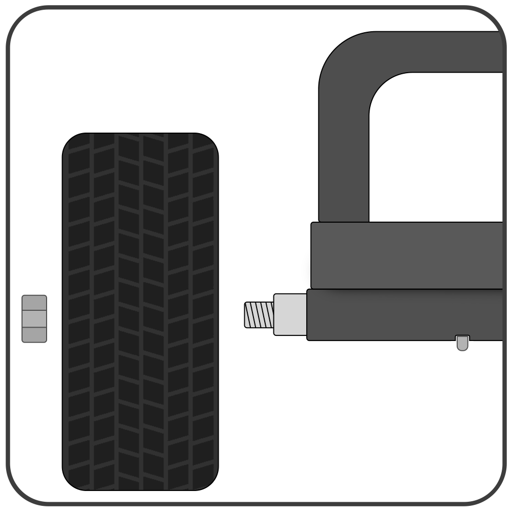 Figure 1
 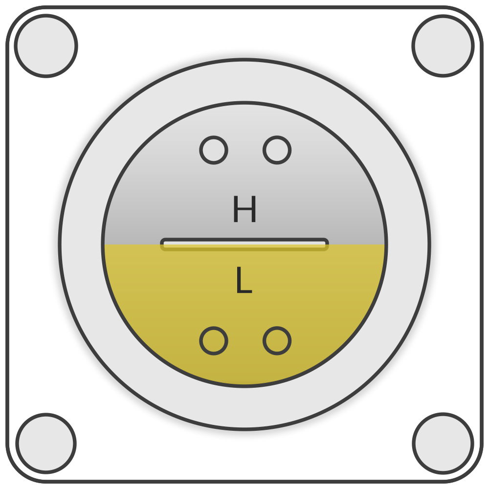 Figure 2
 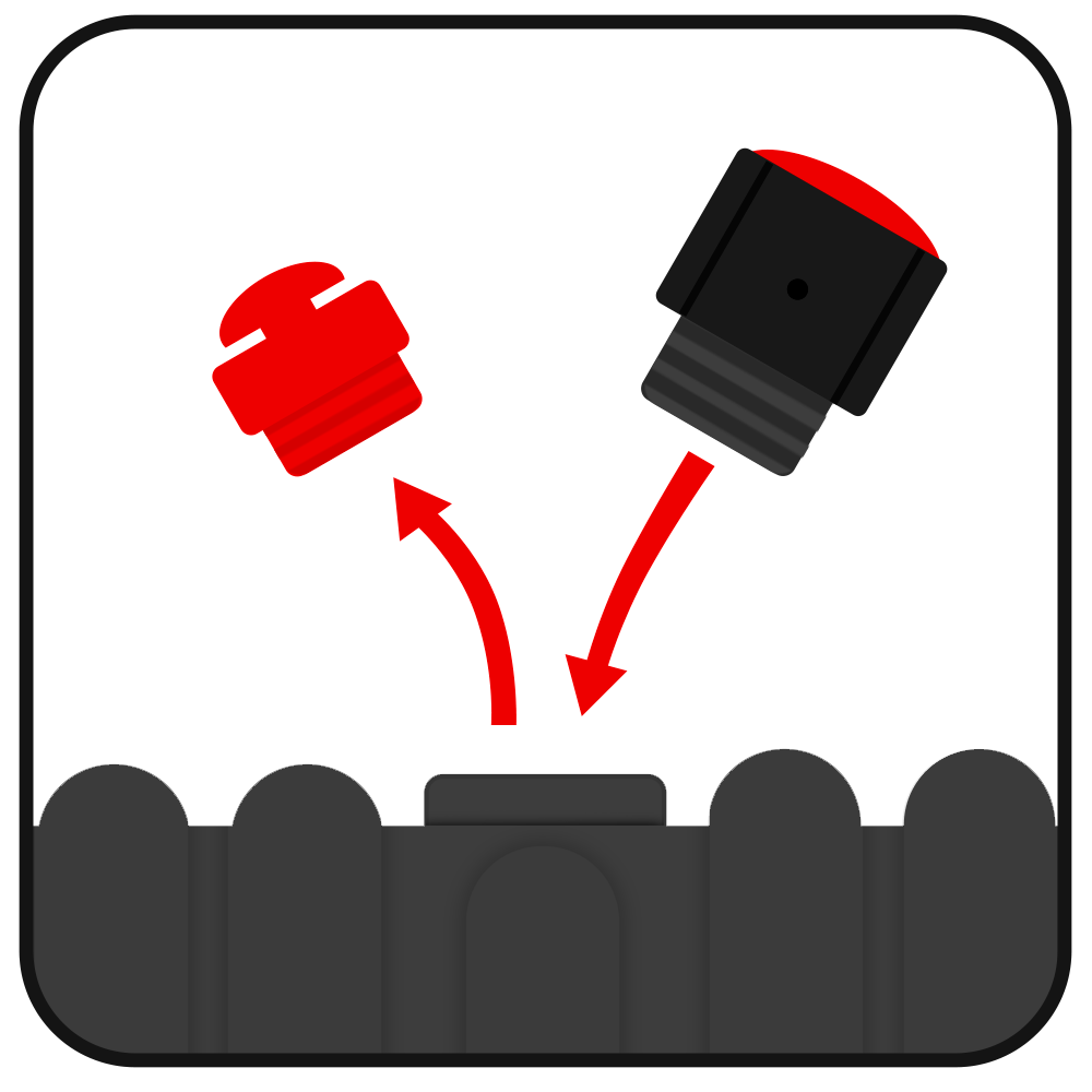 Figure 3
Attaching Unloader Valve:
Attach unloader valve to pump using the two banjo bolts with the pressure adjuster facing upward, ensure the 2 O-rings are in place at each end of the bolts (see figure 4 & 5). May need to pull the unloader apart slightly to fit bigger pumps with larger spaces between the 2 banjo bolts.
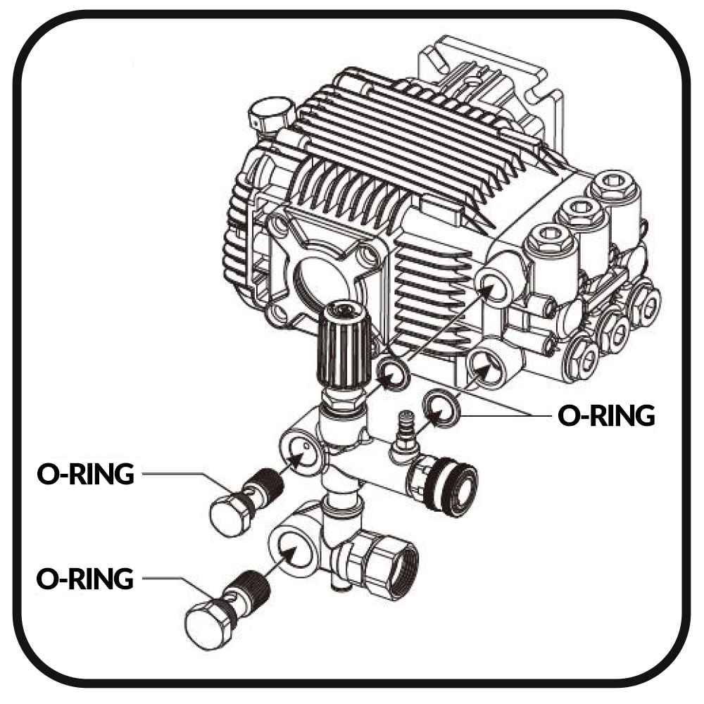 Figure 4
 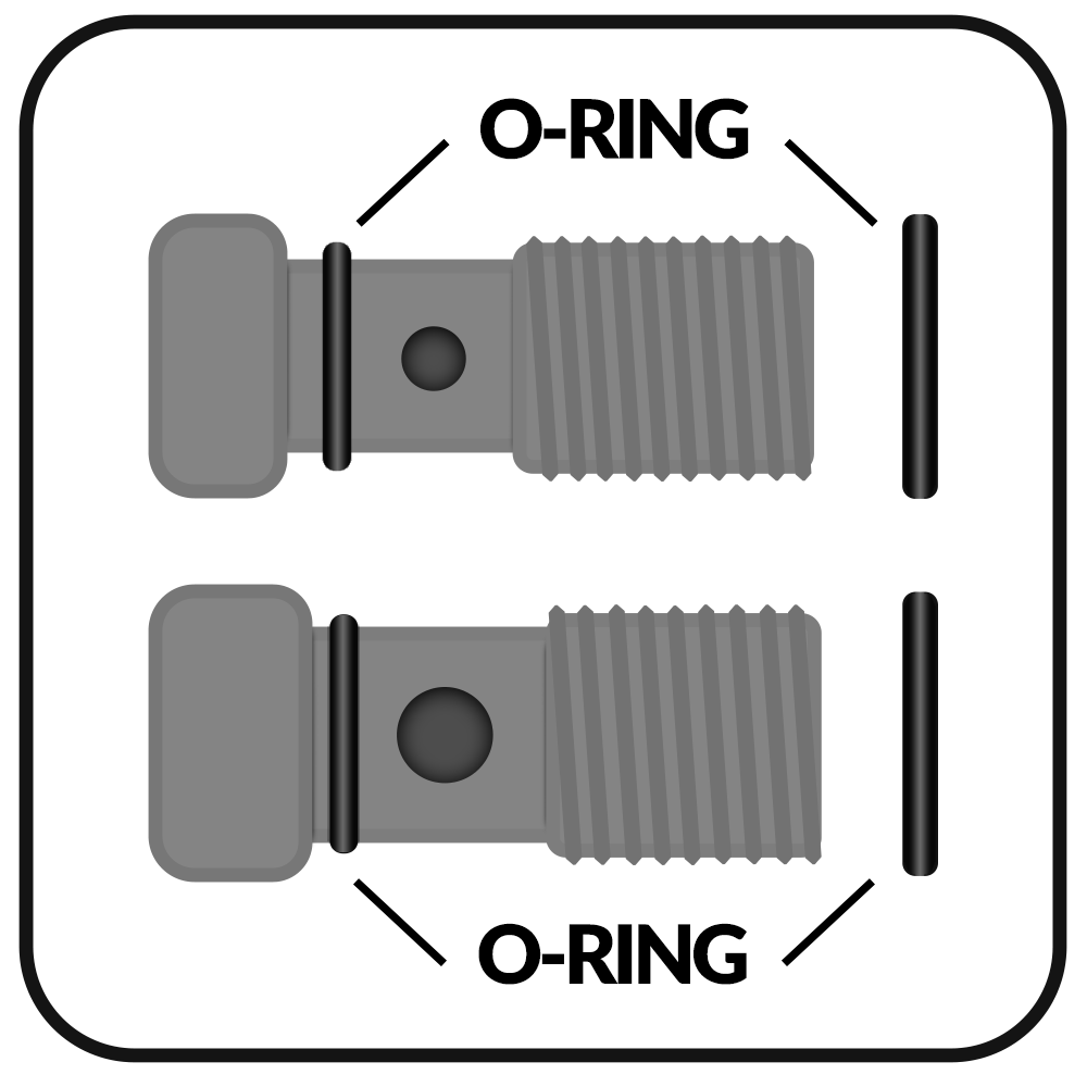 Figure 5
Connecting Power:
The pressure switch control box has 4 sets of wires, 2 pressure switches, power cord to motor (with rings, see figure 9), and power cord to power supply (bare wires, see figure 9).
The power cable with the set of rings are to be connected directly into the motor via the grommet located on the top of the motor. The ground ring is to be connected to the ground screw and the two hot wires connected one on each terminal bridge underneath the nut (see figure 10).
When connecting the control box to your to your power source it will be specific to your facility, either hardwired or by installing a plug for your outlet (plug not included).
The two pressure switches will connect on either side of the pump. The switch with the quick connect fittings will easily connect to the outlet of the unloader valve (see figure 11). The pressure switch with the threaded end will thread directly (use thread tape) in place of the brass bolt in the secondary outlet port located on the right hand side of the pump (see figure 12).
Make sure to reference the above system requirements prior to installation.
Control Box Power Cord:
Brown = Hot Blue = Hot Yellow/Green = Ground
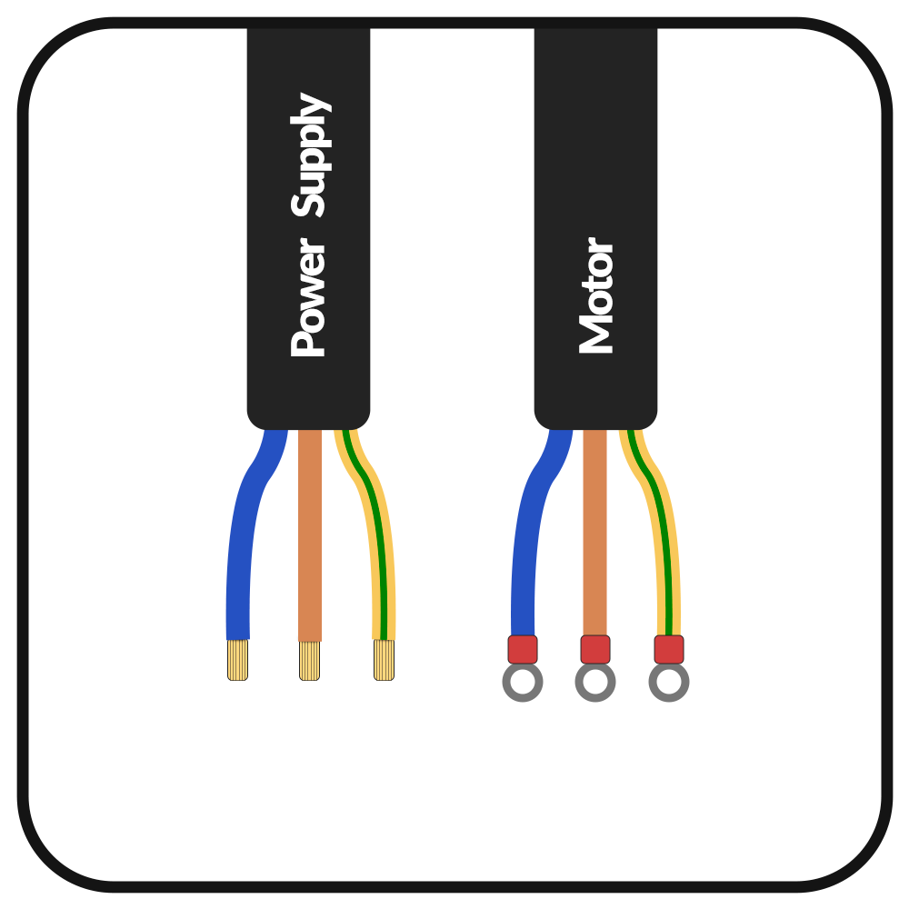 Figure 9
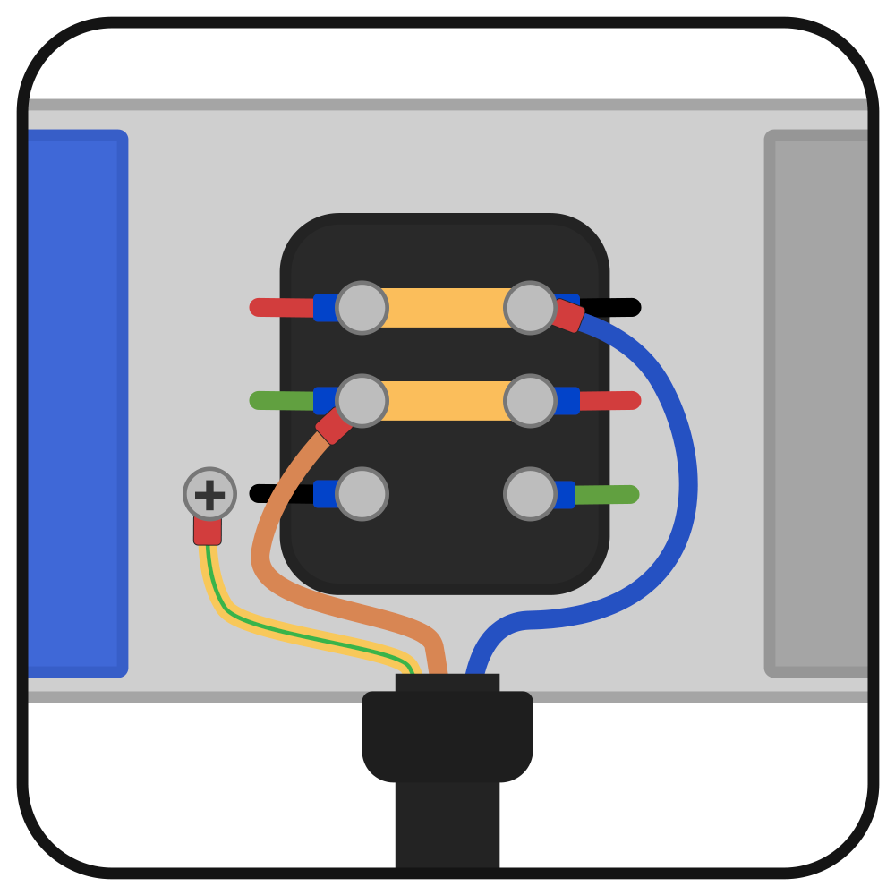 Figure10
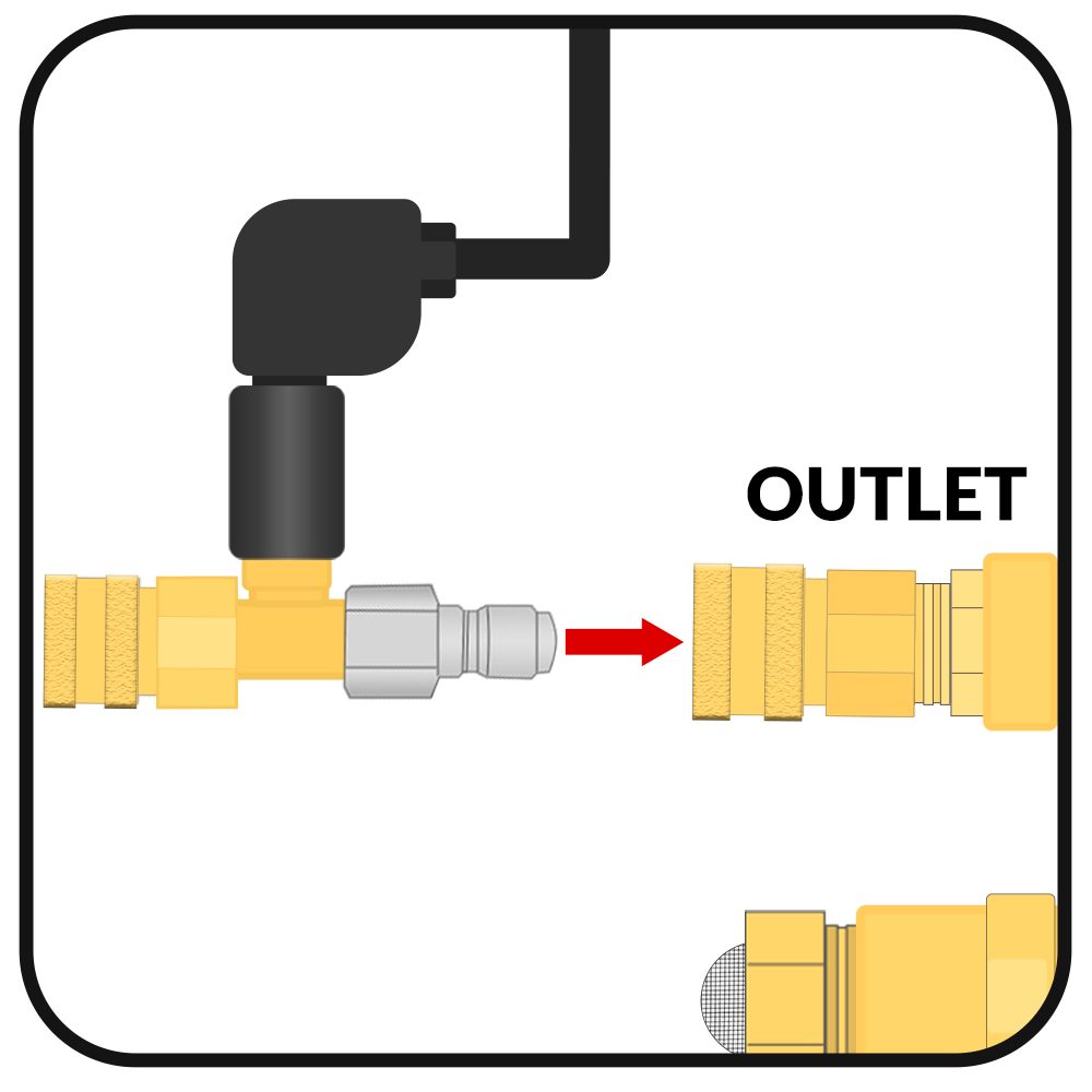 Figure 11
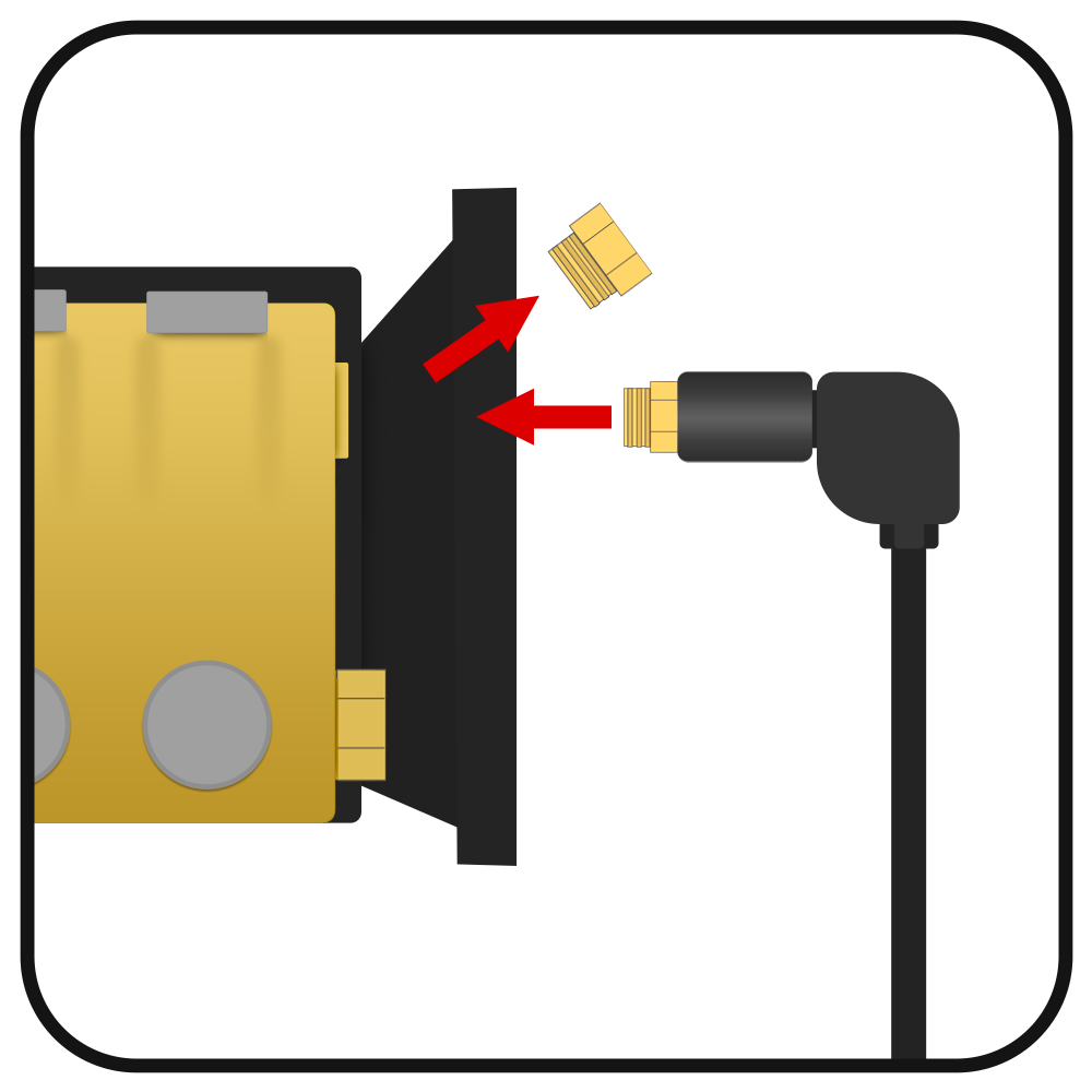 Figure 12
Connecting Water:
Start by connecting the inlet garden hose (not included) to pump's inlet filter with mesh screen (see figure 13). Attach the accessories including high pressure hose, spray gun, quick connect nozzle and other compatible parts to the outlet of the pump/pressure switch beginning with the high pressure hose (see figure 13)
Make sure water is running through the system prior to turning on the pressure washer to purge the lines of air. Avoid running the pressure washer without water at any time.
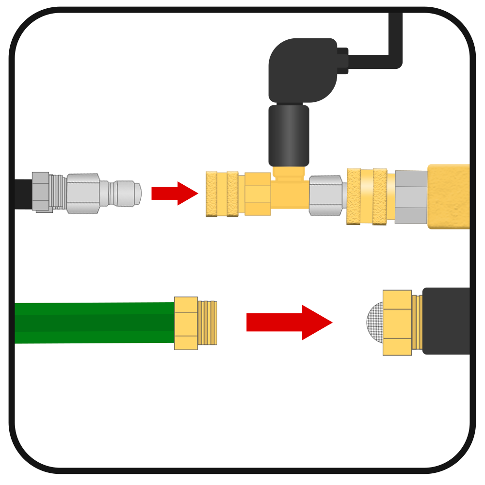 Figure 13
Operation:
Now that all is connected to power and water, hold the trigger down to let water flow out of the end, press the green "ON" button on the control box and the pressure washer will power on. You will now have high pressure flowing from the end of the nozzle, the pressure is adjusted with the unloader valve/pressure regulator by turning the black knob counter clockwise (-) or clockwise (+) as shown on figure 14. DO NOT EXCEED THE PUMP'S RATED PRESSURE. Figure 14
How does the Pressure Switch TSS work?
The Pressure Switch TSS (Total Stop System) operates using two pressure actuated switches to send signal indicating that water is flowing and allowing the controller to power the electric motor of the pressure washer. The pressure switch connected to the quick connect outlet will signal to the controller to power on the motor.
Trigger Pulled = Motor ON
Trigger Released = Motor OFF
When the trigger is released, the timer activates using the pressure switch threaded into the head, which will power down the motor after 5-10 seconds (Timer should never be set no lower than 5 seconds). The controller is still active and when the trigger is pressed again in which it will immediately power the motor on.
The controller must be powered down by pressing the red "OFF" button when pressure washing is complete.
When pressing the green "ON" button, the control box powers the motor immediately stays on until first trigger release or if no trigger is pulled it will start the shutoff timer immediately. The system assumes that you will be operating the pressure washer and water should be flowing out of the trigger prior to powering on the system.
The system is compatible with any spray trigger (except weep style) or any high pressure device to stop the water from leaving the end of your pressure washer hose.
Please note that any and all leaks will affect the operation of the pressure switch controls. If leaking it may not turn off or it will turn on without the trigger being pulled.